UII UPDATE 373 | JUNE 2025
Intelligence Update
AI and cooling: chilled water system topologies

AI and cooling: Part 4
This report (part of the AI and cooling report series) examines the most common chilled water system topologies employed in data centers to support both air and liquid cooling.
Primary-only chilled water loop
In the past, many data centers employed chillers operating at a constant flow. These facility water systems (FWS) controlled water flow to computer room air handling (CRAH) systems in IT rooms using bypass valves (e.g., three-way valves). This method resulted in inefficiencies (high pumping energy and lower return temperature) due to the mixing of supply and return water, but was popular because of its low cost and the limited ability of older chiller controls to handle variable flow.
Today, improved chiller controls and a greater focus on energy efficiency mean that variable flow systems have become standard. These systems adjust pump and chiller speeds as needed, reducing energy use. Although the upfront costs are higher, they offer lower energy costs (a better PUE) and greater flexibility. Older data centers can be upgraded to variable flow by adding modern chiller and pump packages, and removing bypass valves.
Variable-speed chillers and pumps are often installed as integrated packages with built-in controls, connected to the building management system (BMS). Pumps are typically controlled based on the required flow, while chillers respond to the temperature difference between the supply and return water, known as delta-T (ΔT), and the presence of flow. A higher ΔT is beneficial because each unit of water removes more heat, which reduces pumping energy, improves chiller performance and can lower overall system cost.
Variable chiller speeds, however, introduce lag. When there is a significant change in cooling demand, such as with AI compute clusters, chillers and the FWS may not be able to maintain the supply temperature within tolerance levels.
Figure 1 shows a typical variable-flow chilled water loop with thermal storage. Redundant chiller units (labeled as integrated chiller packages on the figure) feed chilled water into a ring (with separate supply and return pipes) that can be maintained without downtime. With increasing IT rack power, thermal storage tanks are also increasingly deployed to stabilize water supply during disruptions, such as transitioning from a utility power failure to engine generators. (Note: The diagrams are simplified and do not include all isolation valves, free-cooling systems (such as dry coolers or cooling towers) and other details.)
Figure 1 Primary-only chiller loop with variable flow
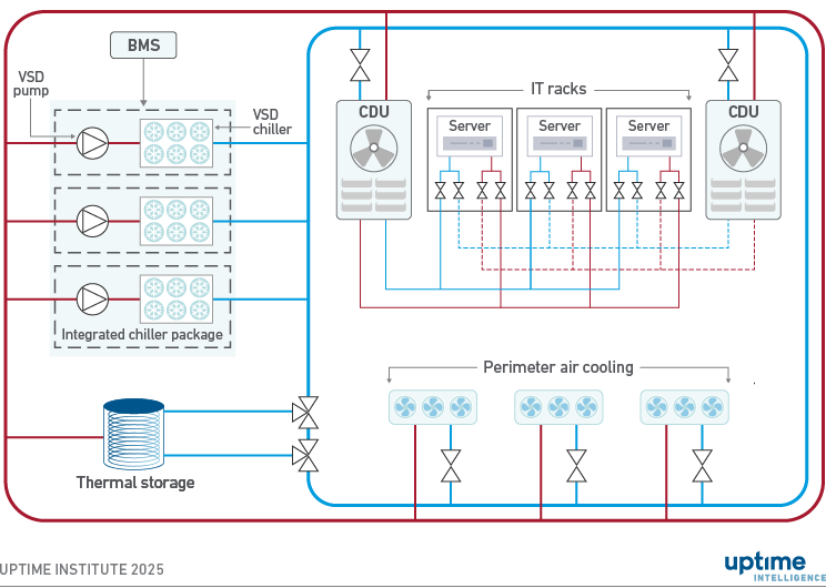
Redundant perimeter air handling units are connected to the variable-flow chilled water loop via two-way control valves, which modulate flow through throttling rather than bypass, as seen in traditional three-way valve configurations. Throttling involves adjusting the valve position dynamically to regulate chilled water flow in response to temperature or pressure changes, which are detected by sensors and controlled by the building management system (BMS) or a local controller.
In high-density direct liquid cooling (DLC) setups, coolant distribution units (CDUs) for cold plates connect to the chilled water loop using two-way valves. For cost reasons, CDUs are commonly deployed in an N+1 configuration when redundancy is expected (rather than 2N as shown in Figure 1). Fan walls are often used instead of standard CRAHs for perimeter air cooling because they can provide more cooling capacity and work well with slightly warmer chilled water, among other reasons.
While DLC systems would allow high operating temperatures (>30°C, 86°F) for the technology coolant side at the cost of higher flows, in practice most installations are more conservative. Uptime Institute commonly sees operators select relatively low CDU supply water temperatures in the 18°C to 24°C (64.4°F to 75.2°F) range. This is because a shared FWS can efficiently support both liquid- and air-cooled IT loads, including rear door heat exchangers. This simplifies the FWS, and provides capacity flexibility for future changes in the cooling mix, in exchange for lower energy performance for DLC loads.
Flexibility is a key business motivation: utilizing shared facility cooling infrastructure for perimeter air cooling and DLC hedges against the uncertainty surrounding future IT deployments. For example, a cooling system can be designed for 60% DLC and 40% perimeter air cooling, with the flexibility to increase DLC to 80% (with 20% air) or go the other way if DLC take-up is limited (under 40% of capacity) and air-cooled loads require 60%. The air-to-liquid cooling ratio will vary between data centers based on their specific IT loads.
Matching flows to various cooling demands is key for power efficiency. The BMS can measure flow using existing differential pressure sensors, electromagnetic flow meters (which are accurate and low-maintenance), or clamp-on ultrasonic sensors for retrofits. Correct flow data is crucial for maintaining energy efficiency, including pump speed optimization, ensuring system reliability, detecting imbalances or failures and ensuring redundancy (e.g., N+1 systems).
Primary and secondary chiller loops
The selection between primary-only and primary-secondary chiller loop configurations is primarily driven by one technical criterion: the required chiller head pressure, which refers to the pressure on the high-pressure side of the chiller system.
Secondary chiller loops are typically implemented to ensure adequate chilled water flow, while optimizing capital and operational expenditure. For instance, rather than using a single loop with large-diameter (e.g., 24-inch diameter) piping, which can be expensive, a secondary loop with a dedicated pump station may achieve the required pressure more economically.
Secondary loops are standard in high-load data center environments (e.g., 6 MW to 7 MW per secondary loop), large data center campuses with multiple buildings, and high-rise facilities exceeding five stories. In multi-building campuses serving various tenants, a dedicated pump station and secondary loop in each building is common to enhance operational independence and tenant flexibility. Less commonly, a centralized pump station can feed multiple secondary loops, functioning similarly to a district cooling system.
Figure 2 shows a chiller system featuring a primary loop and one secondary loop. Multiple secondary loops, each using its own set of VSD pumps, can be added to the primary loop. The use of heat exchangers combined with VSD pumps allows for different supply temperatures on different secondary loops, although this is less common. As discussed earlier, thermal storage can be deployed in series or in parallel with chillers.
Figure 2 Primary loop with constant flow and secondary loop with variable flow
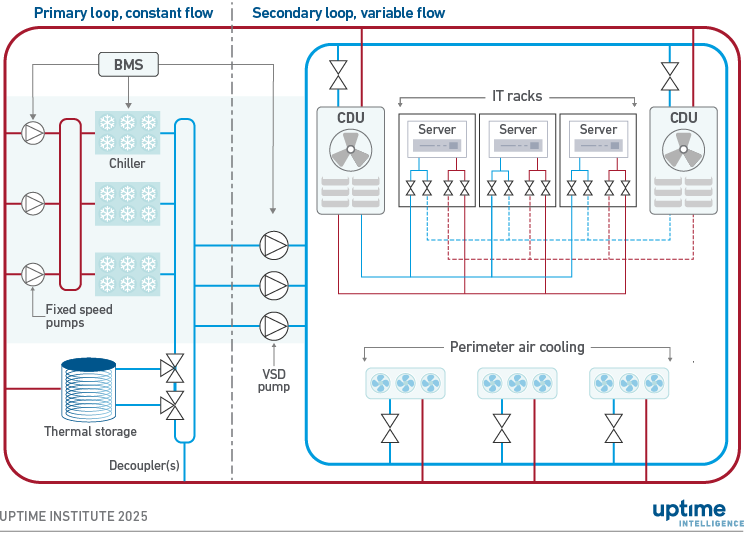
Secondary loops operate with variable flow, supported by redundant variable-speed drive (VSD) pumps. As discussed earlier, the chilled water supply to (and return from) perimeter air handlers and CDUs functions similarly to a primary-only variable-speed system.
The primary loop can be either a constant-flow loop (as shown in Figure 2) or a variable-flow loop. Both approaches are commonly deployed and have their proponents. The traditional, proven approach is to use a constant-flow primary loop. Chillers provide a constant flow, simplifying their control logic and ensuring stable operation.
Potential downsides of constant primary flow occur at partial load, when pump energy is wasted due to excessive pumping, and chiller efficiency can be reduced by low return temperatures, a phenomenon known as the "low delta-T syndrome." Variable primary flow avoids these disadvantages and can therefore provide higher energy efficiency.
Another potential advantage of variable primary is a reduced number of pumps, resulting in lower costs and reduced space requirements. A complication with variable primary systems is that chillers typically require a minimum flow to operate reliably, avoiding chiller shutdowns and failures. Minimum flow rates need to be maintained at all times, for example, by implementing and verifying precise controls (optionally including chiller staging when appropriate) or deploying thermal storage in series with chillers.
Distributed redundant topology
A third topology, a distributed redundant chiller system, is deployed chiefly in specific geographies, including the Middle East and Russia. It is built from multiple, independent cooling systems, similar to how distributed redundant power distribution systems are designed.
In this topology, each chiller utilizes dedicated thermal storage (if applicable) and is typically connected to two to three IT room cooling units, including perimeter air cooling units (commonly fan walls) and/or CDUs. As shown in Figure 3, chilled water supply and return are commonly not organized as a loop. In these cases, each piping system is not concurrently maintainable. However, concurrent maintainability can be achieved by redistributing the full thermal load to redundant cooling systems during maintenance events. VSD pumps and chillers are commonly used to control flow and are sometimes deployed as an integrated package.
Figure 3 Distributed redundant chiller topology
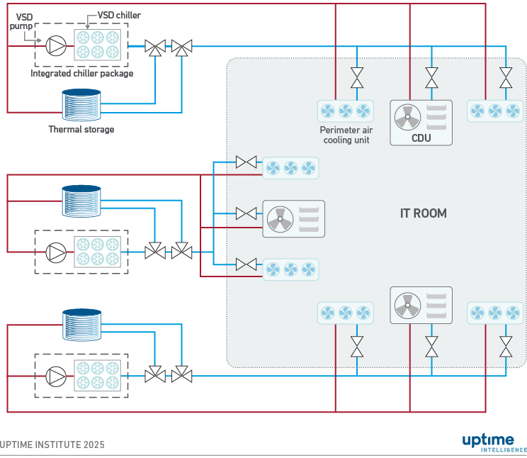
Each IT room is equipped with redundant perimeter air cooling units and/or CDUs, which are fed from different chillers. When an individual chiller system experiences a fault or is taken out of operation, sufficient IT cooling needs to be supplied from perimeter air cooling units and/or CDUs connected to the other chillers. The topology is typically deployed with a group of chillers (e.g., three) supporting multiple IT rooms (e.g., three).
Some operators prefer this topology because they find it costs less, be easier to operate and it avoids single points of failure, even on the chilled water side. However, compared with shared chiller plants, it can be less flexible and less energy efficient because all chillers need to remain on at all times, even at low loads, to ensure redundancy. In the other topologies discussed above, individual chillers can be turned off (chiller staging) when not needed, allowing for more efficient operation at partial loads.
The Uptime Intelligence View
Hybrid air- and liquid-cooled IT loads, outside high-performance computing, are relatively new for mainstream mission-critical data centers, spearheaded largely by AI compute clusters. The pressure to deploy systems quickly to support software development and new business applications means most installations use shared chilled water systems. This leads to inefficiencies in both design and operations. Uptime Institute often sees systems that are overdesigned to support both cooling types, due to the uncertainty of the cooling mix required for each deployment. As operators gain more experience with liquid cooling and a better understanding of how heat loads are distributed between air and liquid systems, informed by business requirements, they will focus more on improving design and energy efficiency to lower capital and operational costs for DLC.
Other reports published by Uptime Institute in this series include:
Part 1: AI and cooling: methods and capacities
Part 2: AI load and chiller systems: key considerations
Part 3: AI and cooling: limits on efficiency gains and heat reuse
The following Uptime Institute experts were consulted for this report:
Chris Brown, Chief Technical Officer, Uptime Institute
Ryan Orr, Vice President, Topology Services and Global Tier Authority, Uptime Institute
Naveed Saeed, Vice President, Global Service Management, Uptime Institute
Carl Hui, Principal Consultant, Service Delivery, Uptime Institute
About the Author

Dr. Tomas Rahkonen
Dr. Rahkonen is the Research Director Sustainability, Europe at Uptime Institute. Rahkonen has spent the last 25 years in positions within the telecommunications, mobile communications, and data center sectors globally, and most recently served as the CTO of Flexenclosure, where he managed the design and delivery of prefab data centers across four continents.
TRahkonen@uptimeinstitute.com